Tampilkan postingan dengan label Robot. Tampilkan semua postingan

Robotics Technology - Controllers

|

The robot connects to a computer, which keeps the pieces of the arm working together. This computer is the controller. The controller functions as the "brain" of the robot. The controller can also network to other systems, so that the robot may work together with other machines, processes, or robots.

Given that the robot arm movement is appropriate to its application, that the arm strength and rigidity meet the payload needs and that servo drives provide the necessary speed of response and resolution, a robot controller is required to manage the arm articulations, its End Effector, and the interface with the workplace. The simplest type of control, still widely used, is "record-playback," or "lead-through". An operator positions arm articulations to desired configurations. At each desired location the articulation encoder positions are recorded in memory. Step by step, an entire work-cycle sequence is recorded. Then in playback mode the sequence is observed and modified.

As applications become more challenging, some jobs require continuous path control of an End Effector. For this action all articulations must be programmed in speeds appropriate to the particular task. This requires programming for the control of the robot. Robots today have controllers run by programs -- sets of instructions written in code. The program sets limits on what the robot can do. These requirements call into play sophisticated computer-based controllers and so-called robot languages. These languages permit a kind of robot control known as hierarchical control, in which decision making by the robot takes place on several levels. These levels are interconnected by feedback mechanisms that inform the next higher level of the status of previous actions. The advantage of a general-purpose robot arm is that it can be programmed to do many jobs. The disadvantage is that the programming tends to be a job for highly paid engineers. Even when a factory robot can perform a task more efficiently than a person, the job of programming it and setting up its workplace can be more trouble than its worth. Commotion Systems, a new California firm, is developing easier ways to program robots using pre-designed software modules. For now though, the job of "training" robots is still one of the main reasons that they are not used more. In the future, controllers with Artificial Intelligence could allow robots to think on their own, even program themselves. This could make robots more self-reliant and independent. Angelus Research has designed an intelligent motion controller for robots that mimics the brain's three-level structure, including instinctive, behavioral, and goal levels. The controller, which can be used in unpredictable circumstances, uses a Motorola 68HC11 microprocessor.

Feedback (Closed Loop) Control

Feedback control is a means of getting a system (in our case a robot) to achieve and maintain a desired state by continuously comparing its current and desired state. The desired state is also called the goal state of the system. Note that it can be an external or internal state: for example, a thermostat monitors and controls external state (the temperature of the house), while a robot can control its internal state (e.g., battery power, by recharging at proper times) or external state (e.g., distance from a wall). If the current and desired state are the same, the control system does not need to do anything. But if they are not, how does it decide what to do? That is what the design of the controller is all about. A control system must first find the difference between the current and desired states. This difference is called the error, and the goal of any control system is to minimize that error. In some systems, the only information available about the error is whether it is 0 or non-0, i.e., whether the current and desired states are the same. This is very little information to work with, but it is still a basis for control and can be exploited in interesting ways. Additional information about the error would be its magnitude, i.e., how "far" the current state is from the desired state. Finally, the last part of the error information is its direction, i.e., is the current state too close or too far from the desires state (in whatever space it may be). Control is easiest if we have frequent feedback providing error magnitude and direction. Notice that the behavior of a feedback system oscillates around the desired state. In the case of a thermostat, the temperature oscillates around the set point, the desired setting. Similarly, the robot's movement will oscillate around the desired state, which is the optimal distance from the wall. How can we decrease this oscillation? We can use a smoother/larger turning angle, and we can also use a range instead of a set point distance as the goal state. Now what happens when you have sensor error in your system? What if your sensor incorrectly tells you that the robot is far from a wall, but in fact it is not? What about vice versa? How might you address these issues? Feedback control is also called closed loop control because it closes the loop between the input and the output, i.e., it provides the system with a measure of "progress."

Open Loop Control

The alternative to closed loop control is open loop control. This type of control does not require the use of sensors, since state is not fed back into the system. Such systems can operate (perform repetitive, state-independent tasks) only if they are extremely well calibrated and their environment does not change in a way that affects their performance. We have talked about feedback control so far, but there is also an important notion of feed forward control. In such a system, the controller determines set points and sub-goals for itself ahead of time, without looking at actual state data.

Reactive Control

Reactive control is based on a tight loop connecting the robot's sensors with its effectors. Purely reactive systems do not use any internal representations of the environment, and do not look ahead: they react to the current sensory information. Thus, reactive systems use a direct mapping between sensors and effectors, and minimal, if any, state information. They consist of collections of rules that map specific situations to specific actions. If a reactive system divides its perceptual world into mutually exclusive or unique situations, then only one of those situations can be triggered by any sensory input at any one time, and only one action will be activated as a result. This is the simplest form of a reactive control system. It is often too difficult to split up all possible situations this way, or it may require unnecessary encoding. Consider the case of multiple sensors: to have mutually-exclusive sensory inputs, the controller must encode rules for all possible sensory combinations. There is an exponential number of those. This is, in fact, the robot's entire sensory space (as we defined earlier in the semester). This space then needs to be mapped to all possible actions (the action space), resulting in the complete control space for that robot. Although this mapping is done while the system is being designed, i.e., not at run-time, it can be very tedious, and it results in a large look up table which takes space to encode/store in a robot, and can take time to search, unless some clever parallel look up technique is used. In general, this complete mapping is not used in hand-designed reactive systems. Instead, specific situations trigger appropriate actions, and default actions are used to cover all other cases. Human designers can effectively reduce the sensory space to only the inputs/situations that matter, map those to the appropriate actions, and thus greatly simplify the control system. If the rules are not triggered by mutually-exclusive conditions, more than one rule can be triggered in parallel, resulting in two or more different actions being output by the system. Deciding among multiple actions or behaviors is called arbitration, and is in general a difficult problem. Arbitration can be done based on

  • fixed priority hierarchy (processes have pre-assigned priorities)

  • a dynamic hierarchy (process priorities change at run-time)

  • learning (process priorities may be initialized or not, and are learned at run-time, once or repeatedly/dynamically)

If a reactive system needs to support parallelism, i.e., the ability to execute multiple rules at once, the underlying programming language must have the ability to multi-task, i.e., execute several processes/pieces of code in parallel. The ability to multi-task is critical in reactive systems: if a system cannot monitor its sensors in parallel, but must go from one to another in sequence, it may miss some event, or at least the onset of an event, thus failing to react in time. Now that we understand the building blocks of a reactive system (reactive rules coupling sensors and effectors, i.e., situations and actions), we need to consider principled ways of organizing reactive controllers. We will start with the best known reactive control architecture, the Subsumption Architecture, introduced by Rod Brooks at MIT in 1985.

The Subsumption Architecture

The following are the guiding principles of the architecture:

  1. Systems are built from the bottom up

  2. Components are task-achieving actions/behaviors (not functional modules)

  3. Components can be executed in parallel

  4. Components are organized in layers, from the bottom up lowest layers handle most basic tasks

  5. Newly added components and layers exploit the existing ones

  6. Each component provides and does not disrupt a tight coupling between sensing and action

  7. There is no need for internal models: "the world is its own best model"

Here is a rough image of how the system works: If we number the layers from 0 up, we can assume that the 0th layer is constructed, debugged, and installed first. As layer 1 is added, layer 0 continues to function, but may be influenced by layer 1, and so on up. If layer 1 fails, layer 0 is unaffected. When layer 1 is designed, layer 0 is taken into consideration and utilized, i.e., its existence is subsumed, thus the name of the architecture. Layer 1 can inhibit the outputs of layer 0 or suppress its inputs. Subsumption systems grow from the bottom up, and layers can keep being added, depending on the tasks of the robot. How exactly layers are split up depends on the specifics of the robot, the environment, and the task. There is no strict recipe, but some solutions are better than others, and most are derived empirically. The inspiration behind the Subsumption Architecture is the evolutionary process, which introduces new competencies based on the existing ones. Complete creatures are not thrown out and new ones created from scratch; instead, solid, useful substrates are used to build up to more complex capabilities.

Behavior Based Control

Behavior-based systems (BBS) use behaviors as the underlying module of the system, i.e., they use a behavioral decomposition. Behaviors can vary greatly from one BBS to another, but typically have the following properties:

  1. Behaviors are feedback controllers

  2. Behaviors achieve specific tasks/goals (e.g., avoid-others, find-friend, go-home)

  3. Behaviors are typically executed in parallel/concurrently

  4. Behaviors can store state and be used to construct world models/representation

  5. Behaviors can directly connect sensors and effectors (i.e., take inputs from sensors and send outputs to effectors)

  6. Behaviors can also take inputs from other behaviors and send outputs to other behaviors (this allows for building networks)

  7. Behaviors are typically higher-level than actions (go-home rather than turn-left-by-37.5-degrees)

  8. Behaviors are typically closed-loop but extended in time (this is often a consequence of #7 above)

  9. When assembled into distributed representations, behaviors can be used to look ahead but at a time-scale comparable with the rest of the behavior-based system

Behavior-based systems are not limited in the ways that reactive systems are. As a result, behavior-based systems have the following key properties:

  1. The ability to react in real-time

  2. The ability to use representations to generate efficient (not only reactive) behavior

  3. The ability to use a uniform structure and representation throughout the system (so no intermediate layer)

The key challenge is in how representation (i.e., any form of world model) can be effectively distributed over the behavior structure. In order to avoid the pitfalls of deliberative systems, the representation must be able to act on a time-scale that is close if not the same as the real-time parts of the system. Similarly, to avoid the pitfalls of the hybrid systems approach, the representation needs to use the same underlying behavior structure as the rest of the system. Note that behavior-based systems can have reactive components to them, i.e., not every part of a behavior-based system needs to be involved with representational computation. In fact, many behavior-based systems did not use complex representations at all. As long as they use behaviors (not just rules), they are BBS.

Robotics Tutorials -Advanced- Programming-Multitasking

|

One of the most powerful features of the BasicX operating system is its ability to multitask. This means it can run several tasks at the same time. It's possible to divide large programs into smaller manageable tasks that can communicate with each other.

There is more information in the BasicX documentation about multitasking, this is a brief tutorial that aims to outline a simple implementation of multitasking and not re write the BasicX manual.

The following sample of code simply turns the onboard red and green led's on and off but hopefully demonstrates how multitasking is implemented in the BasicX programming language.

Task 2 switches a global variable, led, between 0 and 1. Task 1 looks at the global variable and toggles the red and green led's according to its value.

Processing time is given to other functions by calling the sleep command. We use the main procedure to call the tasks using the call task command, and then we enter an infinite loop which shares the processor time around all of the active tasks.

dim led as byte
dim stacktask1(1 to 32) as byte
dim stacktask2(1 to 32) as byte

sub main()
calltask "task1", Stacktask1
calltask "task2", Stacktask2

do
call sleep(2.0) 'do nothing and give all time to other tasks
loop

end sub

sub task1()
do
call sleep(0.0) 'allow other tasks to run

if(led=1)then 'turn on/off led
call putpin(25,1)
call putpin(26,0)
end if

if(led=0)then
call putpin(25,0)
call putpin(26,1)
end if
loop
end sub

sub task2()
do 'Set global variable LED
call sleep(1.0)
led=1

call sleep(1.0)
led=0
loop
end sub

Multitasking has some draw backs to sequential programming; mainly multitasking software generally uses more memory as each process is allocated its own stack. Also, because the processor is frequently switching tasks software can run slightly slower. However these are small limitations when compared to the powerful system of multitasking.

Robotics Tutorials - Beginner - Programming Introduction

|

This is an introduction to programming using the BasicX micro controller, if you have never programmed before this will help you on your way. More experienced readers should still skim through this to get the basics of the language.

Programming is a common language between you and your Robocore, it lets you tell it what to do. In robotics, programming is necessary to make machines that can work by themselves, without human intervention. These are called autonomous robots.

1) Lets start by connecting your Robocore to the power supply and the serial port of your computer, and loading up the BasicX software.

2) When this is loaded, click on the Monitor Port menu and select the COM port that the Robocore is connected to (probably COM1). The Download Port menu should be set to the same COM port.

3) Click the editor button. A window should open asking for a filename. Just type a name for your first program, lets say Demoprog. It will tell you that the file does not exist, so do you want to create it. Click yes.

Now lets write our first program!

To test that the BasicX is working, we will make it send a message back to your computer. This is done using the debug.print command.

Type the following program into the editor window (or copy and paste it). The first and last lines should already be present, if they are just copy the middle line.

Sub main()

debug.print "Robocore test: Everything is working"

End Sub

Before we can download to the BasicX we need to set the chip preferences. This basically tells the chip what we want to be doing with each pin (input, output etc). To do this click on the project menu, followed by chip (or the F7 shortcut). We can leave everything as it is for now so just click on OK.

Now click on the Compile menu and select Compile and Run (keyboard shortcut F5) This will send the code to the Robocore. Going back to the main BasicX window, you should see the text ' Robocore test: Everything is working ' appear on the screen.

The Sub main() and End Sub commands tell the Robocore where the program begins and ends.

The debug.print command is very useful for telling us what the Robocore is doing, in the next case we will see more of its capabilities.

Now we will make the Robocore solve an equation for us. To do this we will need a variable. This is a value stored under a name in the memory of the Robocore. We will give this variable the name ' answer '.

Sub main()

Dim answerI As integer ' declaring

Dim answer As string ' variables

answerI = 5*5 ' doing the maths

answer=Cstr(answerI) 'convert to printable format

debug.print "5 times 5 is "; answer 'print answer

End Sub

Run the program as before and you should get the computer telling you the answer.

This program shows that you can print values from your program to the screen using debug.print just by adding a semi-colon and the variable name after the "text", this is very handy for example when testing sensors.

The program also uses comments, these have no effect on the program but allow us to add information about each line of the program. The computer ignores everything written on the line after an apostrophe (').

This program has also introduced us to variables, the topic for the next tutorial in the programming series

MECHANICS - ROBOT CHASSIS CONSTRUCTION

|


Robot Chassis Construction Tutorial
Robot Part Mounting

This robot tutorial should help you with the mechanical aspect of building your very first robot. You should have already read my build your first robot tutorial before moving on to this tutorial.


Design
When I first started building my first robot, someone much more experienced than me once said paraphrased, "if you build a mechanically crappy robot with expert programming and control, you will only get a crappy robot; build a mechanically professional robot with crappy programming and control, you will still get a well built robot." Its very good advice which I still use today.

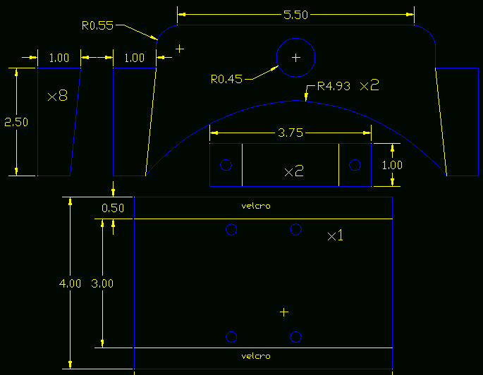
Planning. Would you say someone who plans his future will have a better future? YES! I cannot emphasize any more for you to design your robot out on paper (or computer) first. This means plan out everything, such as what material to build your robot out of<, where to put every screw, how you will attach your sensors - EVERYTHING. You will save money and time, and will have a better constructed robot too. To do this, you should draw all your parts out to dimension, mark your holes, and understand how all your parts connect.

Designing With CAD (click to enlarge)

Use fewer and simpler parts! You will probably quickly realize that the fewer parts your robot has, and the simpler they are, the less you will have to design, make, and pay for. As you design your parts, always consider how you will actually manufacture these parts. Don't use unneccessary or over complicated features, or designs you do not have the tools to make or are really hard to make. Fewer and simpler parts also mean a smaller chance for mistakes in your design. K.I.S.S.

Use off-the-shelf parts. When you purchase a part, it costs money. However there is a good chance that the off-the-shelf part is better than anything you can design and build yourself. Off-the-shelf parts are already well engineered, designed, and tested. This means there is less likely to go wrong on your robot, and less time and effort you need to spend to finish it. How much is your time worth? No point in spending 20 hours making a ghetto circuit when you could buy a high quality one for just $20. Ask yourself if the price of a part is greater or less than your willingness and ability to make the part yourself.

Do not use more than 2 or 3 different screw types. There was a robot I once had to work on that another engineer built. He used a different screw type for every part! I had to use like 10 different unlabeled hex wrenches and 2 different screwdrivers to assembly/dissasemble it. Even worse, he had to purchase 10+ different boxes of screws! If you can make your entire robot out of only the very common 4-40 screws, you are on the right track.

Robot Frame Bottom (click to enlarge)

Frame
The frame of your robot is the basic structure to which you attach everything else. It is probably the largest part of your robot, so make sure it is made of a light weight rigid material such as aluminum or HDPE. I recommend reading those tutorials as well.

Materials
If you are like how I was my first 3 years of building robots, you are probably super cheap and incredibly poor. Robot parts are expensive. Don't even pretend you can make a robot out of parts just lying around your house. Check out my tutorial on funding your robot. To summarize, expect to spend about $10-$50 per robot motor, about $20 on frame material, wheels about $8, and about $10 on miscellaneous nuts and bolts. You can try to search garbage bins and other old stuff for this, but you may or not be lucky. You might be able to find a few reasonable good motors, but it might be much harder to find two of the same motors. Just don't build a crappy robot because cereal box cardboard is the only material you can find!

Mounting
When a beginner asks 'how do I attach my robot part?' what they are really asking is 'what is the best way to mount this part?'. Every part on a robot has a different method of mounting. This is due to obvious constraints such as placement, weight, size, function, etc. So I will go over each of the parts you may want to mount and tell you one or two of the best ways to do this.

Robot Wheels


Wheel Basics
Wheel diameter. When buying (or making) your wheels you want to put your motor into consideration. For a start, there is torque and velocity. Large diameter wheels give your robot low torque but high velocity. So if you already have a very strong motor, then you can use wheels with larger diameters.
Servo's already have good torque, so you should use larger diameter wheels. But if your motor is weak (such as if it does not have any gearing), you want to use a much smaller diameter wheel. This will make your robot slower, but at least it has enough torque to go up a hill! Another dumb mistake someone can make is buying a wheel that has a diameter close to or less than the motor diameter. For example, if you have a 1" diameter motor, and a 1.5" diameter wheel, you have a .25" ground clearance ( (1.5"-1")/2=.25" ). How high is the tallest object you want to go over?

Wheel texture. The texture of your wheel is very terrain dependent. A common mistake for beginners is to ignore the texture of the wheel. If your wheel is too smooth then it will not have much friction. This is a serious issue with omni-wheels. An all plastic omni-wheel works poorly compared to an omni-wheel that uses rubber for the side wheels. Overly smooth robot wheels would likely skid while accelerating and braking. However a wheel that is really rough, such as a foam wheel, has higher friction with the ground leading to innefficiency. You also need to consider wear and tear on the wheel.

Wheel width. You do not want it too wide as it causes increased resistance to rotating the wheel on a surface. I once used a 1" foam wheel on a concrete surface and it was very poor at rotating.

DC Motor Output Shaft

Wheel center hole diameter. This is where you would actually mount the output motor shaft to your motor. So you must know the length and diameter of your motor output shaft so that you may put this shaft into the hole of your motor.

Mounting Your Robot Wheel Techniques
Jamming. Lets start with a basic wheel attached to a basic motor. If the wheel does not have a center hole, just drill one out slightly smaller than the diameter of the shaft of your motor. Make sure the hole is perfectly centered!!!! Then you can fill the hole with a little superglue, and finally press fit (jam, if you will) the motor shaft into the wheel. Perhaps use a little more superglue around the edges.

Servo Wheel Mounting. Mounting a wheel onto a servo is fairly easy, and only requires a little drilling. When you purchase a servo, you also get a bunch of other little goodies with it. One of the items is called a servo horn. This is usually a black/red circular, X shaped, or I shaped plastic piece that attaches to the output shaft of the servo. So what you do is attach the wheel to this servo horn, then just screw the servo horn as designed into the servo. In the images below, I drilled two holes into my wheel, 2 holes into the servo horn (the red X thing), and screwed 2 screws into it to hold them together. Then I just attached the servo horn to my servo output shaft with a 3rd screw.

Robot Servo Omni-Wheel Robot Servo Foam Wheel

This servo wheel mounting method, with slight modification, can work for other motors too. Just make your own custom 'servo horn' with a custom hole designed to fit your motor output shaft.

Purchasing Wheels
The best robot wheels are actually hobby RC aircraft wheels. Strange, huh? Anyway, there is a huge variety of them online for you to choose from. Just go to any RC hobby website. For example, I have bought several wheels from this online RC hobby store.


Motors
There are huge varieties in motors. But for your robot I will assume you are using a basic
DC motor. Make sure you get a motor which already has a gear box attached, as it makes your robot much better controlled, more efficient, and stronger. Designing your own gearing and/or chain systems can and will cause you headaches. My first attempt at it was a miserable failure . . . I recommend against trying it.

Motor Mounting
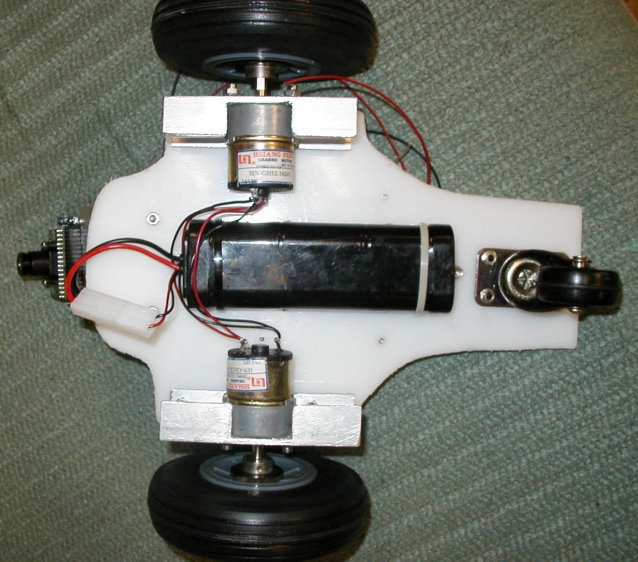
To mount any type of motor to your chassis you will need to use an L shaped bracket. For a DC motor, all you need to do is take a sheet of aluminum, drill two holes in two of the corners, drill two more holes on the other half to match the motor screw holes, then bend the entire piece in a 90 degree angle. This particular image I had found a U shaped piece of aluminum in some bin, I cut it to size, and just drilled the appropriate holes to attach it to my white HDPE chassis.

Robot Motor Mount


Servo Mounting
To mount your
servo to your chassis, once again you will use the little baggie of goodies that came with the servo. You should have two black cube looking things with holes in it. There will be three holes in front and a single hole on the bottom. Your servo should also have four mounting holes, two on each side. Using screws, attach the front of the black things to each side of the servo. As shown in the image below, then attach your robot base with two more screws to the bottom hole of the black thingies. This particular robot used a thin reinforced sheet of aluminum as the base with two drilled holes for the mounting screws.

Robot Servo Mount

And the completed mounted servo and wheel configuration . . .

Servo and Wheel Mounted on Robot


Mounting Robot Batteries
Mounting your
batteries is very simple. As long as you are using an RC battery pack (such as NiCad or NiMH, you can simply mount your batteries to your robot using strips of velcro. This is the velcro that has a sticky tape side and a velcro side. The advantage to this mounting method is that you can easily swap out your batteries for freshly charged ones - great if you are in a robot competition. You can also group multiple batteries together using zip ties. This is an example of a velcro strip taped to a NiCad battery pack:

Robot Velcro Battery Mount


Electronics
Mounting your electronics to your robot can potentially be tricky. If you're lucky, your
microcontroller has holes for screws or something other method of mounting. For this Cerebellum microcontroller (pictured below) I drilled holes into my HDPE robot base, then screwed short metal spacers into the HDPE. Then all I had to do is put my screws through the Cerebellum screw holes and screw them into the spacers.

Robot Electronics Mount

Things to keep in mind when mounting your electronics . . . Keep your electronics high up on your robot. It probably weighs little, so you want the heavier items using the space closer to the ground. You want to keep it out of splashing dirt too. Also keep in mind you probably want certain sensors and other sensitive electronics to stay away from your motors as electronic noise could cause interference. Lastly, plan out your wiring on your chassis - have routing holes drilled through your chassis beforehand, for example.


Mounting Sensors
Mounting sensors is very much a case-by-case basis. What makes mounting sensors difficult is that you are very limited on where you can place them onto your robot. They must be away from noisy motors, and probably at the front/sides of your robot. You must also keep them protected so that collisions and dirt wont damage your sensors too. If your robot is a line follower, you have to keep your sensors at an exact distance from the ground or risk bad data - even when the ground is uneven! If you are lucky, your sensor has screw holes in just the right place at just the right angle. But in my experience this is very unlikely. Unfortunately I have not yet mastered the art of mounting sensors (because of the huge variety of them), but I can go over a few tricks. So you must get creative, build a mount, use a little glue . . . you get the picture.

Here (click to enlarge) you see a homemade aluminum mount for a sonar transducer and another mount on a servo for two Sharp IR Rangefinders. The sonar mount is aluminum bent at 90 degrees with a few screw holes drilled into it, and plastic spacers to prevent any shorting of the circuit board with the aluminum. The IR Rangefinder mount is aluminum with double sided sticky tape holding the sensors onto the aluminum plate.

Sonar and Sharp IR Mounting (click to enlarge)


Hacking RC Car Frames (the cheating method)
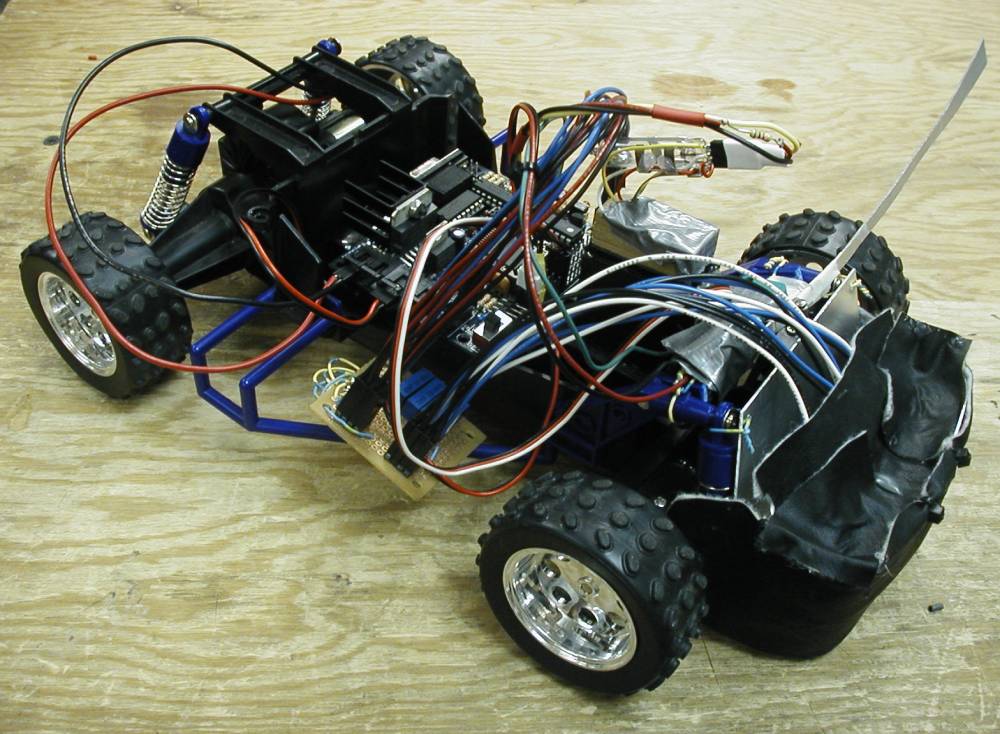
Hacking a toy remote controlled car or tank is a great way to get a professionally built robot chassis with much less work. In this image (click to enlarge) I took a $10 car, hacked the motor wires, and attached all my electronics to it. When buying an RC vehicle, understand that you want a high quality motor so I suggest to avoid the cheap $10 toys. Get something nice if you are going to spend any money on your robot. Notice that you do not need a wireless car! Make sure that the car you will purchase uses a servo for it's rack-and-pinion steering, or you will have to place in your own. I placed my own servo into this cars' steering mechanism so it's definitely possible, but it took time/effort and wasn't perfect. The servo is the easiest way to do any steering system because it has position control.

RC Robot Hack (click to enlarge)

Robot Tank Treads
I have never actually built tank treads onto a robot before - mostly because I have been told, and I fully understand, how difficult this task can be. The best way to get treads for your robot is to get a motorized toy tank and hack it into a robot like you would for any RC car. In this robot I ripped off the top part of the tank, drilled screw holes into the plastic, and screwed on a flat sheet of HDPE. From there you can mount whatever you want onto the HDPE - electronics, sensor setups, etc. I also ripped out the guts and used the empty space inside to store my happy little NiMH battery. I built this robot in less than 5 hours (minus programming and testing). It's that easy!

RC Tank Robot Hack

ROBOT SENSOR INTERPRETATION

|


Robot Sensor Graph

Robot Sensor Interpretation
Most roboticists understand faily well how sensors work. They understand that most sensors give continuous readings over a particular range. Most usually understand the physics behind them as well, such as speed of sound for sonar or sun interference for IR. Yet most do not understand how to interpret sensor data into a mathematical form readable by computers. Roboticists would just make case based situations for their sensors, such as 'IF low reading, DO turn right' and 'IF high reading, DO turn left.' That is perfectly ok to use . . . unless you want fine angle control. The other problem with case based programming is if your sensor reading bounces between two cases, your robot will spass out like crazy (oscillate). Most amazingly, to do fine angle control is actually almost just as simple.

There are only 3 steps you need to follow:

  • Gather Sensor Data (data logging)
  • Graph Sensor Data
  • Generate Line Equation

The first step is incredibly simple, just somewhat time consuming. Graphing just takes minutes. And generating the line equation is usually just a few clicks of your mouse.

Gather Sensor Data
This is fairly straight forward. Do something with your sensor, and record it's output using Excel. If you have a range sensor (such as sonar or Sharp IR), record the distance of the object in front of it and the range data output. If you have a photoresistor, record the amount of light (probably arbitrarily . . . # of candles maybe?) and the sensor data from it. If you have a force sensor, apply weight to it, record the weight, and yes, the data. This is very simple and probably brain deadening easy, but there are a few things you will have to watch out for.

First is non-continuity. Some sensors (such as sonar and Sharp IR) do not work properly at very close range. Stupid physics, I know.

The next is non-linearity. For example, your sensor readings may be 10, 20, and 30. But the distance might be 12cm, 50cm, and 1000cm. You will have to watch for these curves. Usually however they occur only near the minimum and maximum values a sensor can read.

Then there is sensor noise. Five readings in the same exact situation could give you five near yet different values. Verify the amount of sensor noise you have, as some sensors can have it fairly bad. The way to get rid of noise is get a bunch of readings, then only keep the average. Make sure you test for noise in the actual environment your robot will be in. Obvious, but some desktop robot builders forget.

The last issue you will have is the number of data points to record. For perfectly linear sensors you only need to record the two extremes, and draw a line between them. However since this is almost always not the case, you should record more. You should always record more points the more non-linear your sensor is. If your sensor is non-linear only at certain cases, record extra points just in those cases of concern. And obviously, the more points you have recorded, the more accurate you can get your sensor representation. However do you really need 10,000 points for a photoresistor? Its a balance.

Graph Sensor Data
Ok now that you have all your data recorded in two columns in Excel, now you need to graph it. But this is simple.

1) First scroll with your mouse and highlight the cells with data in the first column.
2) Then hold Ctrl and scroll the cells in the other column of data. You should now have two columns seperately highlighted.
3) Next click the graph button in the top menu.
4) A window should open up. Select XY (Scatter). Then in Chart sub-type select the middle left option. Its the one with curvy lines with dots in them. Click next.
5) If you want to compare multiple robot sensors, use the Series tab. Otherwise just use the Data Range tab. Make sure the 'Series in: Columns' is selected. Click next.
6) Pick the options you want, label your chart, etc. Click next and finish. A chart should now appear.
7) Still confused? Download my excel sensor graph examples.

There are some possible graphs you may see with your sensors:
Linear Sensor

This above graph is of a linear sensor. There is a straight line, so a simple 10th grade y=x*c+d equation can predict distance given a data value.

Non-Continuous Sensor

This above graph is non-continuous and non-linear. You will see crazy stuff happen at the beginning and end of the graph. This is because the sensor cannot read at very close distances or very far distances. But it is simpler than it looks. Crop off the crazy stuff, and you will get a very simple non-linear x=y^2 line. You basically need to make sure that your sensors do not encounter those situations, as a program would not be able to distinguish them from a normal situation.

Odd Graphed Sensor

Although this above graph looks simple, it can be a little tricky. You actually have two different lines with two different equations. The first half is an x=y^2 equation and the second half is a linear equation. You must do a case based program to determine which equation to use for interpreting data. Or if you do not care about accuracy too much, you can approximate both cases as a single linear equation.

Generate Line Equation
After determining what kind of graph you have, now all you need to do is use the excel trendline ability. Basically this will convert any line into a simple equation for you.

1) If there is no non-continuities (kinks in the graph), right click the line in the graph, and click 'Add Trendline..." If you do have a non-continuity, seperate the non-continuous lines and make two graphs. That way each can be interpreted individually. If you do not care about error, or the error will be small, one graph is fine.
2) Now select the Trend/Regression type. Just remember, although more complex equations can reduce error, it increases computation time. And microcontroller usually can only handle linear and exponential equations. Click OK and see how well the lines fit.
3) Now click the new trendline and click 'Format Trendline.' A new window should appear.
4) Go to the Options tab and check the box that says 'Display equation on chart.' Click OK.
5) There you have it, your equation that you can use on your robot! Given any x data value, your equation will pump out the exact distance or light amount or force or whatever.

SENSORS - ACCELEROMETER

|


Accelerometer Module

An accelerometer measures acceleration (change in speed) of anything that it's mounted on. How does it work? Inside an accelerator MEMS device are tiny micro-structures that bend due to momentum and gravity. When it experiences any form of acceleration, these tiny structures bend by an equivelent amount which can be electrically detected. Today, accelerometers are easily and cheaply available, making it a very viable sensor for cheap robotics hobbyists like you and me.

Watch a demo I made of using a microcontroller and an accelerometer to control a servo:

Applications for Accelerometers
Accelerometers are very important in the sensor world because they can sense such a wide range of motion. They're used in the latest Apple Powerbooks (and other laptops) to detect when the computer's suddenly moved or tipped, so the hard drive can be locked up during movement. They're used in cameras, to control image stabilization functions. They're used in pedometers, gait meters, and other exercise and physical therapy devices. They're used in gaming controls to generate tilt data. They're used in automobiles, to control airbag release when there's a sudden stop. There are countless other applications for them.

Possible uses for accelerometers in robotics:

  • Self balancing robots
  • Tilt-mode game controllers
  • Model airplane auto pilot
  • Alarm systems
  • Collision detection
  • Human motion monitoring
  • Leveling sensor, inclinometer
  • Vibration Detectors for Vibration Isolators
  • G-Force Detectors

Axis of Acceleration
The tiny micro-structures can only measure force in a single direction, or axis of acceleration. This means with a single axis measured, you can only know the force in either the X, Y, or Z directions, but not all. So if say your X-axis accelerometer endowed robot was running around and ran into a wall (in the X direction). Your robot could detect this collision. But if say another robot rammed into it from the side (the Y direction), your robot would be oblivious to it. There are many other situations where a single axis would not be enough. It is always a good idea to have at least 2 axes (more than one axis).

Accelerometer Axis of Acceleration

Gravity
Gravity is an acceleration. A such, your accelerometer will always be subject to a -9.81 m/s^2 acceleration (negative means towards the ground). Because of this, your robot can detect what angle it is in respect to gravity. If your robot is a biped, and you want it to always remain balanced and standing up, just simply use a 2-axis accelerometer. As long as the X and Y axes detect zero acceleration, this means your robot device is perfectly level and balanced.

Accelerometers, Rated G
When you buy your accelerometer, you will notice it saying something like 'rated at 2g' or '3g accelerometer.' This is how much g force your sensor can handle before breaking. Gravity accelerates objects at 1g, or 9.81 m/s^2. For examplke, if your robot is moving at 1g upwards, then that means you sensor will detect 2g. For most robotics applications a 2g rating will be fine. So why not just get the highest rating possible? The lower the rating, the more sensitive it will be to changes in motion. You will always have a more fine tuned sensor the lower the rating. But then again, more sensitive sensors are more affected by vibration interference.

Calculate Acceleration and Angle wrt Gravity
To calculate the magnitude of acceleration for a
single-axis accelerometer

    acceleration_max = sqrt(x^2) = x

2-axis accelerometer

    acceleration_max = sqrt(x^2+y^2)

3-axis accelerometer

    acceleration_max = sqrt(x^2+y^2+z^2)

To calculate the detected force on an accelerometer due to gravity:

    Force_gravity = -g*cos(angle) (depends on starting axis of sensor)

Angle of Gravity wrt Robort Axis

Chances are you would have no need to measure the force, but if you reverse the equation you can calculate the angle by knowing the detected force:

    cos(sensor_value*conversion_constant / -g)^-1 = angle

Availability and Cost
The MEMS IC's are easily available and very affordable. However they all require support circuitry and come as surface mounts. I highly discourage buying an IC and doing your own wiring. However there are many already setup accelerometer packages you can buy. For example, Dimension Engineering has a great plug and play dual axis accelerometer which requires no additional support circuitry. There are several other great sensors out there, some as a 3-axis, and now some even with built in rotation sensor gyros!

Wiring Requirements
Any accelerometer package will have a power and ground line, and a single output analog pin for each axis of acceleration. Some of the sensors come with additional features/pins, read their datasheets.

Additional Tips and Uses
Placing an accelerometer on a mobile robot that experiences bumps can trigger the accelerometer unintentionally. Use a capacitor to smooth out output over several hundred milliseconds (testing required) to prevent this. Also, read the interpret sensor data tutorial to enhance your accelerator sensor accuracy.

PROGRAMMING - DATA LOGGING TUTORIAL

|

code

Data Logging
Data logging is the method of recording sensor measurements over a period of time. Typically in robotics you will not need a datalogger. But there are times when you may need to analyze a complex situation, process large amounts of data, diagnose an error, or perhaps need an automated way to run an experiment. For example, you can use a data logger to measure force and torque sensors, perform current or power use measurements, or just record data for future analysis.

Parts of a Data Logger
Typically, data loggers are very simple devices that contain just three basic parts:

    1) A sensor (or sensors) measures an event. Anything can be measured. Humidity, temperature, light intensity, voltages, pressure, fault occurrences, etc.

    2) A microcontroller then stores this information, usually placing a time-stamp next to each data set. For example, if you have a data logger that measures the temperature in your room over a period of a day, it will record both the temperature and the time that temperature was detected. The information stored on the microcontroller will be sent to a PC using a UART for user analysis.

    3) And lastly the data logger will have some sort of power supply, typically a battery that will last at least the duration of the measurements.

HyperTerminal
HyperTerminal is a program that comes with Windows and works great for data logging. Back in the day it was used for things such as text-based webpage browsing and/or uploading pirated files to your friends over the then super fast 56k modems.

HyperTerminal Data Logger

I will now show you how to set HyperTerminal so that you may record data outputted by a microcontroller through rs232 serial.

First, you need your microcontroller to handle serial data communications. If it has a serial or USB cable attached to it already, then you are set to continue.

Next, you need a program that reads and prints out sensor data to serial as in this example:

printf("%u, %u, %lu\r\n", analog(PIN_A0), analog(PIN_A1), get_timer1());

If you are interested, feel free to read more with the printf() function tutorial and the microcontroller UART tutorial .

The time stamp isnt always necessary, and you can always add or remove ADC (analog to digital) inputs. Note that the get_timer1() command must be called right before, during, or directly after the sensor readings - or the time recorded will be meaningless. Also, use commas to separate output data values as already shown. I will explain the importance of this later.

Steps to Logging With HyperTerminal
Now open up HyperTerminal
Start => Programs => Accessories => Communications => HyperTerminal
You should see this window:

HyperTerminal Data Logger

Type in a desired name and push OK. The icon doesn't matter.

HyperTerminal Data Logger

Now select a COM port, while ignoring the other options. Push OK.

HyperTerminal Data Logger

In the COM properties, select the options you want/need depending on the microcontroller and serial communications setup you have. Push OK. Chances are if you just change the Bits per second to 115200 and leave the other options as default it should work fine. To make sure, check your C code header for a line that looks something like this:

#use rs232(baud=115200, parity=N, bits=8, xmit=PIN_C6, rcv=PIN_C7)

Now in the menu,
select Transfer => Capture Text...
create a text file, and select it in the Capture Text window
click Start

Now connect your microcontroller to your computer (by serial/usb) and then turn the microcontroller on.

Next you want to tell HyperTerminal to Call. Select the image of the phone:

HyperTerminal Data Logger

Finally, tell your microcontroller to start logging data, and you will see the data appear on screen. Even if you do not plan to save your data, this can be a great feedback tool when testing your robot.

HyperTerminal Ouput Data

When logging is completed, click the disconnect button:

HyperTerminal Data Logger

Then select Transfer => Capture Text => Stop

You should now have a .txt file saved with all your data. But you're not done yet!

Rename the file to a .csv, or Comma Separated Value (CSV) file format. What this does is allows you to open the file in Excel with each value seperated by columns and rows, making data processing much easier. Now you may interpret the sensor data any way you like.

Additional Info On Data Logging
There are many ways to log data, depending on the situation. There is event based data logging, meaning that it only records data when a specific single-instant event occurs. This event could be a significant change in sensor output or a passing of a user defined threshold. The advantage of this method is that it significantly reduces data that needs to be stored and analyzed.

The other method is selective logging, which means logging will occur over just a set period of time (usually a short period of time). If for example you want to analyze an event, your data logger would start logging at the beginning of the event and stop at the end. The advantage of this method is that you can get high resolution data without wasting memory.

Can I Buy a Data Logger for My PC?
Of course. They are called DAQ, or Data Acquisition devices, and have a lot of neat built in software and hardware to make things easier for you. But they can get costly, ranging in the $100's.

ADVANCED ELECTRONICS COMPONENTS TUTORIAL FOR ROBOTS

|

ROBOT BATTERIES

|


Various Batteries

About Batteries
With the advent of portable personal electronics, from cell phones to mp3 players, to laptops and even watches, there has been a massive surge in battery research within the last decade. No longer are your robots limited to bulky low power non-rechargeable batteries, and instead today there is a large assortment to suit your robots' demands. Also visit the tutorials for battery monitoring circuits and robot power regulation.

Ratings
How are batteries rated? With any battery you will see a voltage and a power rating. Battery voltages can be somewhat complicated. When fully recharged, a battery will often be 15% above its voltage rating. When fully discharged, about 15% below its rating. A fully charged battery will also immediately drop below its rating when driving heavy loads, such as a DC motor. To increase battery voltage, wire multiple of them in series.

Batteries also cannot supply an infinite current. So expect batteries of different types but equal voltages to have different current outputs. To increase battery current output, wire multiple of them in parallel. This is why batteries often come in assembled packs of smaller cells. So when using a battery, make sure your circuit handles changes in battery voltage. For the power rating you will see something like 1200mAh. mAh means miliamps per hour. So if it is 1200mAh, that means the battery can supply 1.2 amps for one hour. Or 2.4 amps for 30 minutes. Or .6 amps for two hours. You do the math.

Whats the difference between mA and mAh?
mAh is how much current it 'stores', while mA is the max power it can give.

For example 1500mAh means it can give your robot 1.5 A for one hour before the battery dies. Or 3A for 30 min. Or 6A for 15 min.

While 1500mA means it can give your robot 1.5A until the cows come home, but no more than that.

Notes on Parallel Batteries
You must be very careful when wiring batteries into parallel. If you do not follow these following rules, your batteries will do whats called self discharging. This is when one battery charges another battery in parallel, resulting in high inefficiency, overheating, and damage.

When you put two batteries together in parallel that do not have equal charges, self discharging occurs. You must make sure that both batteries are the same exact type, and you should only charge and discharge them while connected in parallel. You also should not combine an old battery with a new battery, even if they are the same type, as charge/discharge rates change with age.

Battery Calculator To better help you, check out the battery selection calculator to aid you with your robot specs.

Energy Calculator Also, I encourage you to read the robot energy tutorial, and try out the energy calculator to do the math for you.

note:
Battery technology is rapidly improving, so it is possible that this tutorial can be out of date in some places. I will do my best to keep it updated.

Alkaline | Fuel Cell | Lead Acid | Lithium | NiCad | NiMH

Alkaline Battery Alkaline batteries are the most common, easiest to get, and cheapest too. However they are useless, dont buy them. They have low power capacities, are heavy, have trouble supplying large amounts of current in short time periods, and get expensive to constantly replace. The same goes for Zinc-carbon batteries, which suck even more.

Fuel Cell batteries are finally here for robot builders! Although they are still probably too expensive for most hobbyists (~$400). The technology is rapidly improving, so only a few more years until they become cheaply available. Fuel cells are heavily being pursued in research by companies who want to out do the lithium batteries and make billions of dollars. Basically a fuel cell is a tiny engine the size of a battery, and refillable with methanol or ethanol. They are expected to have a two to three times improvement in energy density over today�s Lithium-ion batteries. However it has been estimated that Lithium Ion batteries themselves will probably be developed to have twice the energy capacity as they have today. Fuel Cell

Lead Acid Battery Lead Acid batteries were developed in the late 1800s, and were the first commercially practical batteries. They remain popular because they are easy and inexpensive to manufacture. Rechargeable lead-acid batteries have been available since the 1950s and have become the most widely used type of battery today.
So what does this mean for you? Motorcycle lead acid batteries work great for larger low performance type robots. They are great for solar power robots too. Best of all, they are cheap and available off the shelf. Just remember that lead acid batteries have the serious problem of being very large and heavy, need to always be kept charged, and do not have the high discharge rates as the more modern batteries.

There are three main types of lead acid batteries. Wet Cell (flooded), Gel Cell, and Absorbed Glass Mat (AGM). The Gel Cell and the AGM batteries are specialty batteries that typically cost twice as much as a premium wet cell. However they store very well and do not tend to sulfate or degrade as easily or as easily as wet cell. There is little chance of a hydrogen gas explosion or corrosion when using these batteries. Gel Cell batteries, which are best used in very deep cycle applications, still are being sold but AGM batteries are typically better. In most cases AGM batteries will give greater life span and greater cycle life than a wet cell battery.

80% of all battery failure is related to sulfation build-up. This build-up occurs when the sulfur molecules in the electrolyte (battery acid) become so deeply discharged that they begin to coat the battery's lead plates. The buildup will become so bad that the battery will die. There are several things you need to remember when managing lead acid batteries to prevent battery failure. First, make sure they always remain fully charged. This means recharge as often as possible, and no partial recharging either. Next, batteries not used for awhile will slowly discharge internally, so you need to make sure they are kept fully charged often. For some batteries several times a week. Also, really hot temperatures or subzero temperatures are bad too. And make sure you always use the proper charger and charging rate for the right type of battery.
Lithium (Li-ion) are the new standard for portable power. Li-ion batteries have the same high energy capacity as NiMHs, power output rates of NiCads, and weigh about 20%-35% less. They also have zero memory effect problems, meaning you can recharge whenever. Although lithium batteries are the most advanced for portable power, they are also usually the most expensive. Prices have been significantly dropping lately however, and I predict NiMH and NiCAD types soon becoming obsolete. They are made out of totally non-toxic material, making them safe for cute squirrels and pretty trees. Just remember, lithium ignites very easily, and forms large quantities of hydrogen when put in contact with water, so don't shoot at it or blow it up or anything of that nature. Also, fire extinguishers are usually water based, so dont use them on lithium battery fires. Bad stuff will happen. There are also lithium polymer batteries. This battery type has extremely high current output capabilities (30A+), but less power density than lithium ion batteries. Lithium Battery

NiCad Battery NiCad (Nickel Cadmium) batteries are good for small to medium size range robots. They have the highest current output, are more affordable than NiMH's, and can be recharged within one or two hours. However recharging NiCad batteries is a black art. Ever notice how some older cell phone batteries just do not last as long on a single charge as when you first bought it? This is called memory effect. A NiCad, over many charges, can only store less and less energy after each recharge. To prevent memory effect, whenever you wish to recharge your NiCad, you must first fully discharge it. Just hook up both battery leads to a cute kitten until it stops moving. I guess a motor would work too . . . And remember, NiCad batteries contain toxic cadmium stuff, so save a squirrel and recycle/dispose of it properly.

NiMH (Nickel Metal Hydride) batteries are really neat. Older cell phone batteries were often NiMH. You can recharge them as much as you want, they have good current output, and have the highest energy capacity. I would recommend them for small size robots and for powering circuits. Note, NiMH batteries usually take like 10 hours to recharge depending on various factors. Also, some NiMH batteries have a high self-discharge rate. In other words, leave it for a week or so, and you will find an entirely discharged battery. But fortunately NiMH battaries can last many more cycles than your typical NiCad battery.


©2009 news update come true | Template Blue by TNB